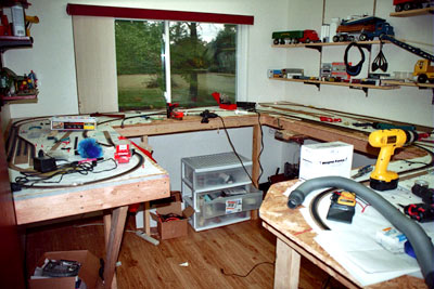
Empire Express, like most other software programs, allows one to print out the layout diagram in 1 to 1 scale. Switching into the page view mode, I was able to see how many sheets of paper it would take. I was also able to see which sheets of paper actually had information on them, and which sheets were in the portion of the room not occupied by the layout. Since my layout is an around the wall plan, I could have virtually covered every square inch of the floor with paper. Since the page view showed pages and page numbers, I was able to selectively print out only those pages with data on them. These pages were trimmed and then taped to the table top. The single line representing the track became the center line for the strips
of cork. At first we tried tacking the cork with track nails to hold it in place as we worked with each section. We quickly stumbled onto a much quicker, and easier, technique. Scrapbooking stores sell a special glue and applicator for mounting pictures. The glue comes in two types, removeable and permanent. The glue is attached to a long strip of paper rolled up in a spool. The spool fits in an applicator shaped much like a pizza cutter. Running the applicator along both sides of the center line transfers the glue to the paper template on the layout. The cork is then laid, using the centerline as a guide. The glue is strong enough to hold the cork in place, but will still release the cork if you need to reposition it. (Is it just me, or does everyone's layout look like a disaster in progress as mine does in the picture above, when a constructioni project is going on?)
Once the cork for an area was down, the track was laid. I used track nails to hold the track (and the cork) permanently in place. I was reluctant to glue the track to the cork roadbed because the cork was being held to the paper templat, not actual top of the layout. Moving the paper template would, in fact, shift the track.
At the very beginning of this project, my son and I had a discussion about the use of decoupling magnets on the layout. I was in favor of using some sort of pick for uncoupling purposes, but my son wanted to be able to uncouple 'remotely'. He plotted out where he thought uncoupling magnets should go and marked the spot on the layout template next to the track.
Referring back to an article that appeared in Model Railroader in late 2003 or early 2004, we purchased a couple of bags of rectangular ceramic magnet from Radio Shack. In locations where magnets were to be used, the cork road bed was removed. Since the magnets were a little bit thicker than the cork, a wood chisel had to be used to create a shallow pocket in the wood table top for the magnets to
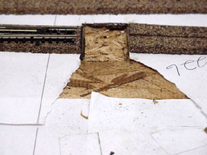
sit in. Because of the polarity of the magnets, two had to be placed side by side to create a magnetic surface wider than the track itself. The cork can be removed and a pocket hollowed out for a magnet even after the track is laid. It is only slightly more difficult to do a magnet install with the track already in place. This picture
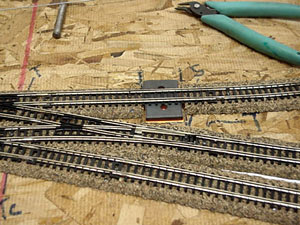
shows the track installed over a magnet. Their is a circular hole in the center of each magnet. Some sort of trackside marker will need to be placed next to the track to show the location of each uncoupling magnet, since they will be hidden with ballast.
Now for some unique operational characteristics we have found after installing the magnets. As indicated in the Model Railroader article, the magnets are strong and do a very nice job on MTL couplers. However, we have found that, for some unknown reason, they will NOT actuate Accumate couplers. (A solid, on piece magnet, will actuate an Accumate coupler, however.) For this reason, we are gradually replacing all of our Accumate couplers with MTL's counterpart.
As you can see in the picture above, the paper template has been cut away. It does, however, still exist under the cork road bed. You can see just a little hint of it between the double track.
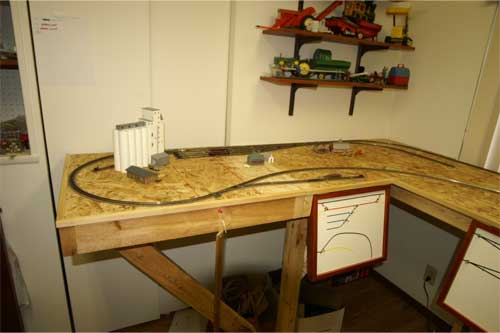
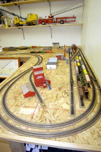
At this point I think all of the track is laid and wired. There have been some changes to the original track plan, as the picture below shows. The original plan called for a
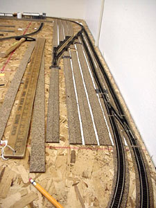
storage yard at the 'top' of the plan, with plenty of open space to the left. The picture above shows the yard, with the beginnings of a locomotive service and storage facility in the background.
The following pictures show the layout as it exists at the indicated date. At this point in time, all trackwork is down and wired. There may be minor changes, but none are foreseen at this time. As you can tell from the photo above, the layout is built on a plywood deck. There is no grade to the track. Low hills and a variety of structures will help to 'hide' parts of the layout to provide more interest to the eye. At this stage of contruction, the structures are being built and placed on the layout. Adjustments in urban areas and rural areas will be made as necessary. When all (or most) of the structures are located, roads and other scenic details will be plotted and the construction of the scenery will begin in earnest. What follows is a brief tour of the layout.
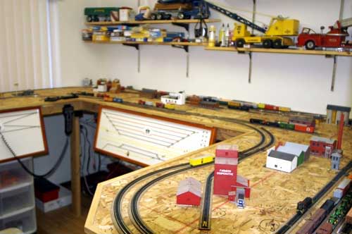
The 'west' leg has a major grain shipping industry towards the back, and a team track in the front. An industrial spur is in the back right of the picture. Scerenery here will be rural, with a small agricultural village represented by a general store, a country church, and a few houses. The grain shipping industry has four sidings designated for incoming empties, outgoing loaded, and the one that runs behind the facility for loading. The team track will serve the small town by the facility, plus agricultural businesses off to the right of the picture.
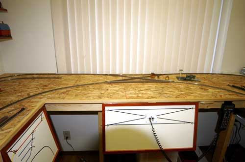
The main feature of the back part of the layout is the diamond which, in effect turns both ends of the layout into reverse loops. A train coming from the left on either track can enter the loop on the right on either track. The direction a train enters the loop will be determined by which sidings and / or industries are going to be switched. Basically this allows for out and back operation from either of the main yards on the layout. Rural, agricultural scenery on the left will blend in with more urban scenery to the fron and center which will help hide the track in the back.
The east and south sides of the layout contain the most of the industries and the main (but small) yards. Industrial spurs run off both ends of the yard on the back wall. That yard, which is double ended, was going to be used for visible staging, with trains startin and ending there in both directions. However, when setting up a method of operations, it was discovered that there was not enough yard space for revenue cars, so this yard became mini classification yard. There is a single ended yard locomotive facility on the south wall. You can see just a tiny bit of it in the lower right-hand corner of the picture.
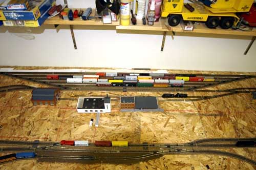
This overhead shot gives a bird's eye view of the staging/classification yard on the east wall. Industrial spurs are in front of it, as well as off of each side of it. In the forground is another portion of the mainline. Again industrial spurs are off to each end. The track in the front with a single blue car on it is an interchange track that connects with both the Illinois Central and the Illinois Terminal railroads off the layout.
This view of the south leg of the layout shows the other yard in the foreground with the locomotive facility in the background. The second of three grain elevators is on a siding here.
As you can see from this quick tour, much work remains to be done. As structures are built and placed on the layout, much tweaking will take place on where agricultural and urban areas are located. Roads, at this time, are simply a figment of my imagination. The next step is to paint all exposed surfaces of the deck with an earth tone paint. Also, it is time to start ballasting the main line. Roads will be indicated with blue painter's tape, which can easily be relocated as necessary.
The layout is not nearly as elaborate as many I have seen, but for the time being, at least, it serves my needs.
This page last updated on 2/5/06