|
|
|
The biggest decision that had to be made about the layout was whether to wire for block control or DCC control. DCC had not been a consideration until recently because of expense and because none of my motive power was DCC compatible. The thought of retrofitting as many as 17 different locomotives for DCC was daunting, to say the least.
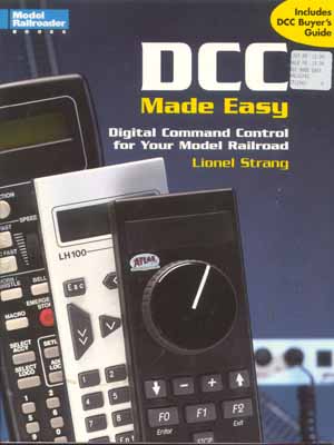
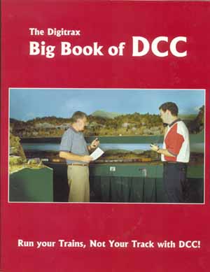
In the beginning of the project, the idea was to use block control and use the Cooler Crawler Throttles from TracTronics. However recent articles in Model Railroader and a visit to the Blissfield Model Railroad Club convinced me to take a closer look at DCC. Two books were a great help. They were DCC Made Easy from Model Railroader and the Digitrax Big Book of DCC.
|
|
|
The book DCC Made Easy is a quick and easy read and, in my opinion, does an excellent job of giving an overview of what DCC is and how it works. The Digitrax book is a great reference book for DCC, even if you are not using a Digitrax system. After much thought and consideration, we decided to use DCC.
DCC Made Easy gives an overview of several different systems. We read the overviews, studied the manufacturers' web sites, and perused other informational websites posted by retailers to decide which system to choose. We would have liked to visit working layouts to see each of the different systems in operation. Unfortunately we were only able to see and 'play' with a Digitrax system, and the CVP Easy DCC system. Both were very nice and had many desirable features. In the end, however, we ended up going with the NCE Powerhouse Pro system. So far, we have not regretted this decision. We have converted four locomotives to DCC at this time and are using the NCE system on the test track.
As mentioned elsewhere, we have decided to use the Tortoise Slow Motion switch machines for most, if not all, of our turnouts. We intend to use DPDT mini-toggle switches mounted in the fascia board to control the turnouts. We also intend to use green and red LED's in the fascia board for a visual indication of each turnout position. The paperwork with Tortoise switch motor is fairly self-explanatory, but it does leave a lot to be desired in the way it suggests wiring the LED's. For one thing, the plans call for the use of 12 volt LED's, which are next to impossible to find. We are experiment with some circuitry using low voltage LED's, perhaps even bipolar rather than separate red and green. When we are satisfied with the way the circuit works, I will post the schematic here.
The first control panel is complete (almost). 3 mm bipolar LEDs were used to indicate switch position. The LED's were placed in series with the toggle switch and the switch motor. The Tortoise switch machine adds enough resistance to the circuit to eliminate the need for a separate voltage dropping resistor. Each circuit has two bipolar LEDs in series with the switch motor, one for each leg of the turnout. In cases where one toggle switch controls more than one switch motor, more LED's are added as necessary.
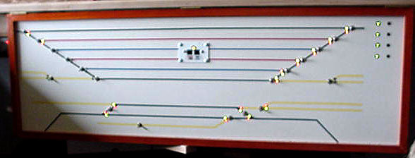
The above photo shows one of four control panels for the layout. LEDs show the position for each turnout. Each set of LEDs is wired in series with a turnout motor and change color when the toggle switch is thrown to select the alternate route.
|
|
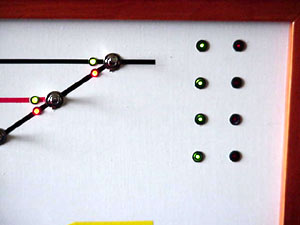 |
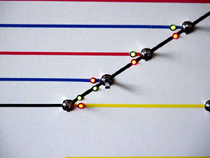
The pictures above show some of the panel detail. The left picture shows a close-up of one side of a staging yard. The bipolar LEDs show the selected route with a green light. The blue lines are for east bound trains, while the red lines are for west bound trains. Yellow lines indicate industrial sidings.
The layout is divided into 4 power districts using circuit breakers. The fourth power district is also a reverse loop. The picture at the right shows a close up of the power district status indicators. These LEDs are wired directly to output pads on the power district circuit board cards. The top three pairs of LEDs are for power districts 1 - 3. The green LEDs are lit if there is power to the district and it is operating normally. The red LED comes on if there is a short circuit in the power district and the controller card has cut power to the district. When a red LED comes on, the corresponding green LED goes out. The bottom pair of LEDs is for power district 4, which is the reverse loop. The green LED indicates normal power and no short. A flashing red LED indicates that the reverse loop controller has kicked in and reversed the polarity of the loop. The red LED will continue to flash until the loop polarity flips back to 'normal'. Because the power district LEDs are being fed with AC track power, a 750 ohm resistor has been placed in series with each LED. Labeling has not yet been added to the control panel.
 |
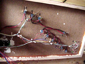 |
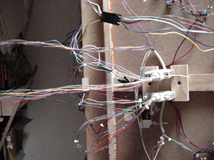
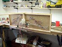
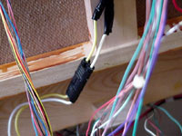
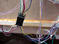
My son decided that we needed to construct the control panels so that they could be easily removed from the layout. They are attached to the layout with hinges that allows them to be swung up vertically with the back facing out (below left). A 3 amp, 12 volt DC power supply is being used to provide power for the Tortoise machines and their LEDs. The power supply is wired to a terminal strip and a separate run for each of the 4 control panels is also connected to the terminal strip. Wiring is done in such an additional power supply could be added easily to the terminal strip, just by removing jumpers, thus effectively creating two wiring busses for the switch machines, rather than the one we currently have. Each power bus run is connect to a control panel with a two-wire polarized plug typical of those found at Radio Shack (below center). We used 25 wire computer cables with DB 25 connectors to connect the toggle switched for the tortoises to the switch machine itself. A six foot cable was cut in half with the wires at the end of one segment going to the switch machines and the corresponding color wires from the other segment going to the LED / toggle switches on the control board. (See above right.) The female db 25 connector was mounted directly to the back of the control panel, with its wires feeding the panel, while the wires corresponding wires from the male connector run directly to the switch motors (above left). A detailed chart has been made of which color pairs feed which switch motors. Finally, the particular control panel illustrated also controls the programing track, which doubles as an industrial siding. In this case, a rectangular, 6 wire, trailer plug was used, in conjunction with a double pole, double throw toggle switch to make the connection. Two input wires come from the programming output of the NCE controller, two wires from the power booster, and the output goes to the track. A simple throw of the toggle switch converts the siding from normal operation to programming. Of course, both rails are completely insulated from the rest of the layout. For this particular control panel. one simply needs to disconnect the 4 connectors to 'free it up' for removal.
 |
 |
 |
Those that are familiar with DCC know that stationary DCC decoders can be used to control the switch motors. However, this adds an additional load on your DCC power booster. It also gives you another whole set of parameters to control with a hand set that can be rather cryptic. In its favor, however, is the ability to program complicated routes through staging and sorting yards and throwing a multitude of switches with one command. The toggle switches mentioned above were a much less expensive alternative, and present less things to remember with the DCC controller. Turnouts can always be converted to DCC control at a later date.
Our layout will be divided into 4 power districts, one of which will be a reverse loop. (See the track plan section for more details on this.) We are using power district and reverse loop controllers from NCE. Because of this, and because of the maximum number of locomotives operating at any given time, we will not need to purchase additional DCC power boosters. Mainline trackage will have power feeds every 4 to 6 feet. These power feeds will be soldered to the outside of the rail. Likewise, every passing track, siding, and staging track will have its own feed. Separate pieces of track will be soldered together to insure good electrical feed from piece to piece. Insulating gaps in both rails will be used at the power boundaries. Also, the gaps will be staggered at each end of the reverse loop to better trigger the reverse loop power controller.
More information and pictures will be added here as the laying of the track gets under way.
Back to site map.
This page updated Nov 30, 2004