I decided at the beginning that the bench work we constructed would dictate the track plan that we used. This may not have been the correct approach. I am sure that many can make a very good argument for letting the track plan dictate the bench work.
In our case, however, we had limited space to work with, and also had to accommodate the entry door, closet, and built-in book case. We had the choice between building a 4 X 6 island extending out from one wall, or building a shelf around the perimeter of the room. I felt the shelf would give us more flexibility in designing the layout.
I considered 3 different shelf designs in the planning process. The first and third were very similar.
This design lent itself very well to an out and back layout. As I started drawing plans I ended up with a yard and staging area on an upper level next to the door. Trains leaving the upper level moved around the room to an industrial area by the closet and then back to another industrial area and hidden staging on the lower level by the door. While the plan offered many possibilities, I ultimately rejected it for two reasons. First was the thought of building a multiple level layout, when it had been 30 some years since I had done any building - and then only on a 5 X 9 piece of homosote. The second reason was that all of the motive power (mostly Wabash) and building structures that I collected over the past 10 years were aimed at the central Illinois farmland where I grew up. A multiple level layout with tunnels and trackage bridging over trackage was simply not appropriate for my concept of what I wanted. (This was a great excuse - letting me off the hook of admitting I was chicken to tackle something more complicated!)
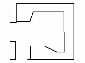
The second bench work foot print I devised allowed for easy access to the built-in bookcase and closet. It also provided for continuous running via an expanded oval around the room. A lift-out bridge provided access to the center of the layout. Minimum radius was 19 inches. The plan called for a suggested industrial area in the corner beyond the closet, visible staging against the wall opposite the closet. There was also an interchange with another railroad, a short line such as the Illinois Terminal Railroad, that served many agricultural industries. This layout had much promise and I was very excited about it, until I started trying to add scenic details to the plan. I then discovered that while I had a lot of track with a multitude of operating possibilities, I had no real room for any scenic materials that make a layout more than just track. I reluctantly abandoned this plan.
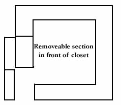
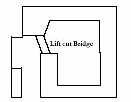
The third attempt at a bench design was actually triggered by an idea for a layout plan published in Model Railroader. The removable section in front of the closet gave more operating space. The resulting plan was a folded dogbone variation that offered a lot of operating potential, but still had many open spaces for creating scenery. It offered the simple, one level, table top design design I was looking for.
Actual details of the track plans for benches 2 and 3 can be found in the track planning portion of this site. Unfortunately, the quick lived plan for bench 1 was done with some demo software that did not have SAVE capabilities enabled. A screen shot printout of the first plan has been lost.
Several factors were taken into consideration in designing the bench work and subsequent table top. I determined that all table tops had to extend from 27 to 31 inches from the wall. This meant the possibility of leaning over and on the table top to reach the far corners. Building with construction grade Styrofoam was thus ruled out. Because I envisioned using under the table mounted turnout machines, the table top could be no more that 5/8 inches thick. I felt that the bench work could be made lighter by using 1 X 4's for the substructure. My son convinced me to opt for the added strength of using 2 X 4's for the substructure. We are probably way overbuilt, but I am sure that an adult could actually walk on the table top with doing any damage to it.
I determined that I wanted to attach a facia board around the front of the layout. A track diagram would be drawn on the facia and toggle switches for the turn outs would be installed. LED's to indicate the turnout position would also be installed. Because of this, we determined that the table top would extend 3 inches into the room beyond the edge of the substructure. This would allow the construction of a framework dropping down 6 - 8 inches from the front edge of the table top to hold the facia board.
Height of the table top was another consideration. Most modelers agree that you should view you model railroad as close to eye-level as possible. Building at an adult's eye-level when standing would effectively block most of the light coming in through the only window. We decided that the table top would be 42 inches above the ground. This put the table top close to eye level when sitting in an office chair on casters. It also put the table top only a couple of inches above the bottom of the window. The bench work along the outside wall, however, would have to be offset to allow for vertical blinds used in that window.
The house is an older house, and as such, does not have perfectly level floors. A point 41 1/2 inches above the floor was marked just to the right of the window. Then, using a 5 foot level, reference points were marked all the way around the room so that the table top would be level. (We found a variance of almost an inch from lowest point to highest point.)
We were now ready to start the construction of the bench work. I was reading the ad inserts in the Sunday paper and discovered that Sears had a powered compound 10 inch miter saw with laser guide on sale for a great price. I convinced my wife that this would be an enormous help in our construction project. So after a quick trip to Sears, construction began in earnest.
I drew in all of the bench work to scale on the computer generated track plan. This way I could be sure, I hoped (we haven't put this to the test yet), that no piece of substructure would interfere with placement of turnout motors.
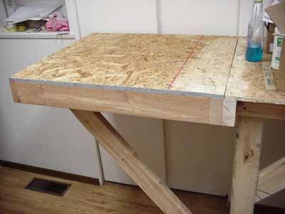
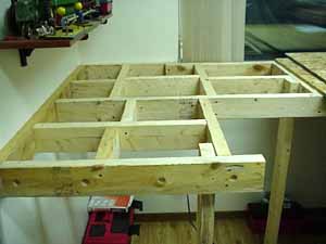
First, 2 X 4's were fastened horizontally to the wall by screwing into studs. Next the outer perimeter of the substructure was created by toe-screwing into the perimeter board and then building out. Legs were cut and place at strategic locations to support the entire substructure. Once the outer perimeter was constructed, cross pieces running from the support piece on the wall to the outer perimeter were installed spacing them as close to 16 inches apart as possible. Then cross pieces running the other direction (parallel to the wall support) were installed. The result was a rock solid foundation. Part of the exposed substructure can be seen in the photo below.
Construction the Extension
As was mentioned earlier, we had many grandiose ideas for how to construct the extension. The idea that we thought we would eventually use was to construct a storage cabinet on castors, the top of which would act as the extension. It could be rolled into place for an operating session, and then rolled away to allow my wife access to the closet. However, when we got the bench work complete and the table top screwed down, we realized that the cabinet would take a large part of the available space in the middle of the room when it was 'rolled out of the way'.
This meant falling back to an alternate plan A. Since the length of the extension was about 6 inches less than the height of the substructure from the floor, I felt the extension framework could be attach to the permanent bench work with two or three heavy duty door hinges. Some sort of a removable brace or braces would hold it in place when operating, then it could be dropped down when not in use. Any structures on the extension would have to be removable, so they would not be damaged when dropped down. After looking at the permanent bench work, however, we realized that this would not work. This was because the permanent bench work ended flush with the closet door. When dropped down, the surface of the extension would extend 4 inches into the closet door space, setting up a situation where my wife would always be running into it. This situation was not conducive to the integrity of the extensions, or to spousal relations.
Fall back to plan B. My son engineered a relatively ingenious system which allowed the construction of a self supporting extension that could be completely removed by one person and then stored on its side under the existing bench work. A detailed diagram of the system, and pictures are shown below.
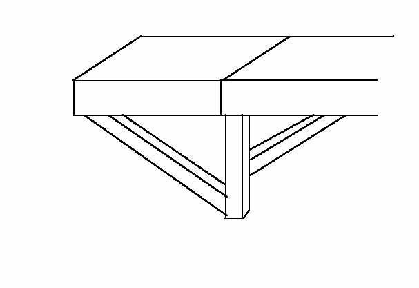
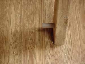
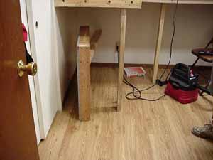
The above illustration is a crude drawing of the extension connected to the end of the permanent bench work. The vertical leg is at the end of the permanent bench work. The diagonal support on the right side of the leg is permanently installed. The diagonal support on the left is hinged where it attaches to the extension substructure, so it can swing up out of the way for storage. A peg made from a 3/4 inch dowel extends from the inside of the permanent leg (below left). A notch cut into the hinged diagonal support fits over the leg (below right).
|
|
|
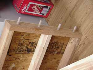
The picture of the bench work substructure towards to top of the page actually shows the end of the permanent bench work where the extension attaches. Notice that there are 4 holes 3/4 inch in diameter drilled into the end of the bench work. There are four dowels permanently installed in the end of the extension that fit into those holes. There is also a bolt that fits through a hole and is secured with a wing nut. This insures the extension is securely attached and hopefully the tracks will always line up.
|
|
|
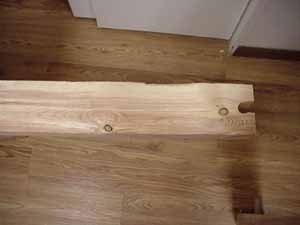
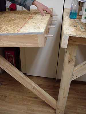
The picture on the left above shows the extension laying on it side. The pegs are clearly visible. If you look carefully just to right of the second peg from the left, you can see the bolt. The picture on the right above shows the extension in the process of being put in place. The hinged brace has dropped down and the notch has been placed on the peg. The pegs and bolt will be inserted into their respective holes on the end of the permanent bench work, and the wing nut and washer assembly firmly tightened onto the bolt.
Looking at the pictures below, the left picture shows the extension secured to the bench work. The right picture shows the extension stored under the bench work.
|
|
|
The final step was to round off the corner of the table top next to the hallway door. This allows enough clearance to enter and leave the room with the extension in place
At this point the bench work is complete. The next step is to prepare the bench work for the laying of the track. A grid of lines, 6 inches apart, will be drawn on the bench work. This will help with the placing of the track. More pictures and documentation will be added as we work on this step.
Back to site guide
Page last updated 5/31/04